- Español
- Português
- русский
- Français
- 日本語
- Deutsch
- tiếng Việt
- Italiano
- Nederlands
- ภาษาไทย
- Polski
- 한국어
- Svenska
- magyar
- Malay
- বাংলা ভাষার
- Dansk
- Suomi
- हिन्दी
- Pilipino
- Türkçe
- Gaeilge
- العربية
- Indonesia
- Norsk
- تمل
- český
- ελληνικά
- український
- Javanese
- فارسی
- தமிழ்
- తెలుగు
- नेपाली
- Burmese
- български
- ລາວ
- Latine
- Қазақша
- Euskal
- Azərbaycan
- Slovenský jazyk
- Македонски
- Lietuvos
- Eesti Keel
- Română
- Slovenski
- मराठी
- Srpski језик


Structure and Principle of Single Shaft Shredder
2021-09-27
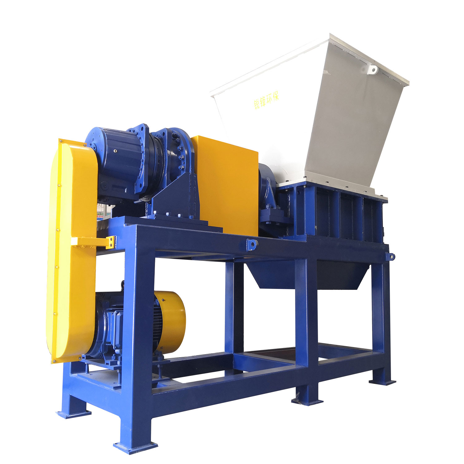
Structure and principle of single shaft shredder
The single-shaft shredder is mainly composed of a blade spindle, a fixed knife, a carrying box, a box bracket, a feeding system, a hydraulic pushing system, a power system, and an electrical control system. Mainly used to shred wood, rubber, plastic, paper and other waste materials.
Features:
It is suitable for shredding materials with strong entanglement, allowing a small amount of light and thin metal objects in the materials;
Lower tool usage and maintenance costs;
Under the same power condition, the price is relatively low compared with the double shaft shredder, the three shaft shredder, and the four shaft shredder;
Easy to change tools;
The size of the material can be adjusted according to the size of the screen aperture;
Equipment maintenance:
Regularly check whether the connection of each connection part on the equipment is loose;
Regularly check the current of the main motor of the equipment;
Regularly check whether the hydraulic system is normal;
Regularly check the wear of the tool;
Structure and principle of single shaft shredder:
1. After the material is fed into the shredder, the pushing box is driven by the hydraulic station to push the material to the knife stick. The knife stick is driven by a power system consisting of a motor, a belt, a pulley and a reducer to shred the material.
2. The power is fixed on the movable knife seat of the knife stick by bolts. When the equipment is running, the material will be shredded by the interaction between the movable knife and the fixed knife; the gap between the movable knife and the fixed knife can be adjusted by adjusting the bolt.
3. The shredded material particles are discharged through the sieve, and the size of the discharged particles is determined by the aperture of the sieve.
The pusher box is driven by a hydraulic station; the rotor rotor is driven by a power system consisting of a motor, a belt, a pulley and a reducer. The pushing box pushes the material to the rotor for shredding.
The movable knife is fixed by bolts and the fixed knife cooperates with the movable knife to shred the material when the power base equipment is running; the gap between the movable knife and the fixed knife can be adjusted by adjusting the bolt. The size of the shredded material particles through the screen can be controlled by changing screens with different apertures.
Single shaft shredder composition
1. Rotor
(1) V-shaped movable knife arrangement-efficient shredding + large shearing force, high output;
(2) DC53 material heat-treated movable knife-how many times can the angle be changed;
(3) Adjustable fixed knife-by adjusting the gap between the movable knife, high wear resistance;
(4) The rotor can be welded with a wear-resistant layer-suitable for processing sandy materials or glass fiber and other materials.
2. Screen
(1) Quickly replaceable screen (12-100mm)-used to control particle size;
(2) The screen bracket is equipped with a safety switch-to prevent the rotor from running when the bracket is opened;
(3) The screen bracket is opened by an air cylinder-set in V800 and larger models for easy maintenance;
(4) Specially designed screens-screens of various structures can be selected according to the type of material.
3. Bearing
(1) High-strength, high-usage system bearings-independently installed outside the box to prevent debris from entering the bearings;
(2) The overall processing of the bearing seat-to ensure the installation accuracy and prolong the life of the bearing;
(3) Cooling device-when processing low melting point materials, a water cooling device that penetrates the rotor through the bearing seat can be selected.
4. Hydraulic station
(1) Two-speed hydraulic system-the pusher box retreats at high speed, which greatly shortens the retreat time and maximizes the output;
(2) Air-cooled device-to maintain the oil temperature of the hydraulic system to meet the needs of continuous production;
(3) The cover is fully sealed-from a safety point of view, a fully sealed cover can be selected when processing wood and other materials.
5. Electric control cabinet
(1) Independent electric control cabinet-Siemens PLC control system, electrical components;
(2) Manual/automatic switching system to facilitate cleaning and maintenance;
(3) Intelligent control system-the rotor will automatically reverse when overloaded, and the equipment will stop automatically when there is no material.